Introduction
Building an MRI suite is one of the most technically demanding construction projects in healthcare facility design. Unlike standard imaging rooms, an MRI room must integrate a Faraday cage for RF shielding, support extreme floor loads, manage complex HVAC requirements through RF waveguides, and coordinate dozens of filtered penetrations — all while meeting the MRI manufacturer's precise specifications.
In the United States, MRI room construction typically involves coordination between the hospital or imaging center, the MRI equipment vendor (GE Healthcare, Siemens Healthineers, Philips, Canon Medical), a specialized RF shielding contractor, the architect of record, structural engineers, and MEP consultants. Each party has specific requirements that must be reconciled during the design phase to avoid costly change orders during construction.
This guide walks through every phase of MRI room construction, from initial site assessment to final commissioning, providing the technical detail needed to plan a successful project.
Site Assessment & Feasibility
Before any design work begins, a thorough site assessment determines whether the proposed location can support an MRI installation. Key factors include:
Electromagnetic Environment Survey
An RF background survey measures the ambient electromagnetic interference at the proposed site. Sources such as broadcast transmitters, cellular towers, nearby MRI systems, electrical substations, and elevator motor rooms can produce RF interference that the shielding must attenuate. The survey results inform the required shielding effectiveness (SE) specification for the Faraday cage.
Structural Capacity
MRI magnets are extraordinarily heavy. A typical 1.5T superconducting magnet weighs between 4,000 and 6,000 kg (8,800–13,200 lbs), while 3T systems can exceed 7,000 kg (15,400 lbs). The floor must support this concentrated load plus the weight of the RF shielding enclosure (typically 2,000–4,000 lbs depending on shielding material choice). Most installations require a reinforced concrete slab rated for a minimum of 500 lbs/sq ft in the magnet area.
Magnet Delivery Path
The MRI magnet is delivered as a single, indivisible unit. The delivery path from the building exterior to the MRI room must accommodate the magnet's dimensions and weight at every point — doorways, corridors, elevators, and turns. Many projects require temporary wall removals or crane access through roof openings.
5-Gauss Line Mapping
The static magnetic field extends beyond the MRI bore in all directions. The 5-gauss (0.5 mT) line marks the boundary beyond which the field is considered safe for the general public and sensitive equipment. This fringe field footprint must be contained within controlled areas — it cannot extend into public corridors, adjacent offices, or parking structures. Modern actively shielded magnets have significantly reduced fringe fields, but passive magnetic shielding with steel plates may be needed in constrained sites.
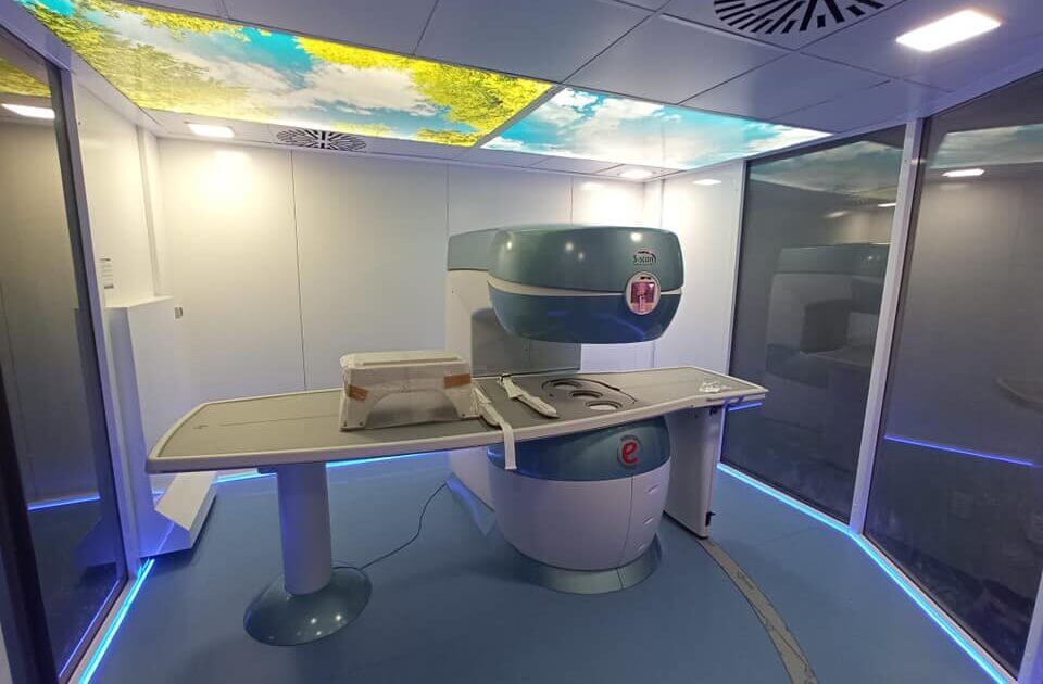
Room Layout & Design
MRI Manufacturer Site Planning Documents
Every MRI manufacturer provides detailed site planning guides for each scanner model. These documents specify minimum room dimensions (typically 30–40 sq m / 320–430 sq ft for the scan room), ceiling heights (minimum 2.9–3.2 m / 9.5–10.5 ft), door opening sizes, and the precise location of the penetration panel relative to the magnet isocenter. Deviating from these specifications risks equipment warranty issues and operational limitations.
Control Room
The control room, separated from the scan room by the RF shielded wall, houses the MRI operator console, electronics cabinets, and the RF observation window. It must have direct line-of-sight to the patient through the shielded window. The control room typically requires 15–25 sq m (160–270 sq ft), with dedicated HVAC to manage heat from the electronics cabinets.
Equipment Room
A dedicated equipment room (or alcove) houses the MRI system's gradient amplifiers, RF amplifiers, and cooling equipment. This room is typically adjacent to the scan room and connects through filtered penetrations. Adequate ventilation and cooling capacity is critical, as gradient amplifiers alone can generate 20–40 kW of heat during operation.
Patient Holding & Preparation
Adjacent spaces for patient preparation, screening (MRI safety questionnaire, metal detection), and recovery are essential for operational workflow. The screening area must include a ferromagnetic detection system to prevent ferromagnetic objects from entering the magnet room — a critical MRI safety requirement per the American College of Radiology (ACR) guidance.
RF Shielding Enclosure (Faraday Cage)
The RF shielding enclosure is the most specialized component of MRI room construction. It forms a continuous, electrically conductive barrier around the entire scan room — all six sides (four walls, floor, ceiling).
Shielding System Types
Modern MRI shielding systems use prefabricated modular panels, typically copper or aluminum sheets bonded to structural substrates (plywood, MDF, or steel). Panels interlock with precision-machined joints and are sealed with conductive gaskets or solder to ensure continuous electrical conductivity. The two main construction approaches are:
- Bolt-together modular systems — panels bolt together with conductive gaskets at every joint. Faster to install and easier to modify later, but joints require careful quality control.
- Welded/soldered systems — panel joints are continuously soldered or welded for maximum RF integrity. Higher SE performance but more labor-intensive and difficult to modify after installation.
RF Door
The RF shielded door is the most mechanically complex and failure-prone component of the Faraday cage. It must provide the same SE as the walls while allowing daily patient access. High-quality RF doors use knife-blade or fingerstock contact systems with pneumatic or manual clamping mechanisms. Door seals require regular maintenance and periodic replacement to maintain SE performance.
Observation Window
The RF shielded observation window allows visual monitoring of the patient from the control room. It typically consists of two or more glass panes with fine copper mesh or transparent conductive coatings laminated between them. Window sizes range from 60 × 40 cm to 120 × 80 cm depending on the design.
Penetration Panel
The filtered penetration panel is the single point where all electrical and data connections pass through the shielded enclosure. It contains Pi-filters and capacitive filters for power lines, signal cables, patient monitoring leads, nurse call systems, and medical gas alarms. The penetration panel location is specified by the MRI manufacturer and must be precisely positioned during shielding construction.
Structural Requirements
Floor Loading
The MRI scan room floor must support several concentrated loads: the magnet (4,000–7,000+ kg), the patient table, the RF shielding enclosure, and interior finishes. A reinforced concrete slab of 200–300 mm (8–12 inches) thickness is standard, with rebar spacing calculated to distribute the magnet's point loads. The structural engineer must review the MRI manufacturer's loading diagram, which shows the exact position and magnitude of each magnet foot load.
Vibration Isolation
MRI gradient coils produce rapid magnetic field changes that generate mechanical vibrations. In sensitive locations — upper floors, buildings shared with research labs or surgical suites — vibration isolation pads or spring-mounted platforms may be required beneath the magnet. The MRI manufacturer specifies acceptable vibration levels, typically below 5 µm peak-to-peak displacement at the gradient switching frequency.
Ceiling Structure
The ceiling above the RF shielding enclosure must support the weight of the ceiling shield panels plus any equipment mounted above (lighting, HVAC ductwork penetrations). The shielding ceiling is typically suspended from the structural ceiling above using non-ferromagnetic hangers (aluminum or stainless steel) within the 5-gauss line.
MEP Systems Coordination
HVAC
The MRI scan room requires dedicated climate control to maintain stable temperatures (typically 18–22°C / 64–72°F) and manage the significant heat generated by the scanner. All ductwork penetrating the RF enclosure must pass through RF waveguides — specially sized hollow tubes that attenuate RF energy below the cutoff frequency while allowing airflow. Supply and return air paths must be carefully planned to avoid short-circuiting and ensure adequate air distribution around the magnet.
Electrical Systems
MRI systems require clean, dedicated electrical power — typically 480V 3-phase in the US — with isolation transformers to minimize electrical noise. All power conductors entering the shielded room pass through Pi-filters in the penetration panel. Emergency power (generator backup) must be provided for the magnet's cryogenic cooling system to prevent helium boil-off during power outages.
Plumbing & Medical Gas
Medical gas lines (oxygen, vacuum, medical air) serving the MRI room must transition from metallic piping outside the shielded enclosure to non-ferromagnetic, non-conductive tubing inside. Copper medical gas piping cannot penetrate the RF shield without proper waveguide or filtered penetration treatment. Inside the 5-gauss line, all piping and fixtures must be non-ferromagnetic.
Fire Protection
Fire sprinkler systems in the MRI room present unique challenges. Sprinkler piping must be non-ferromagnetic within the 5-gauss line (typically brass or copper), and the penetration through the RF enclosure requires waveguide treatment. Pre-action or dry-pipe systems are often preferred to avoid accidental water discharge near the magnet. All fire protection design must be coordinated with the Authority Having Jurisdiction (AHJ) and comply with NFPA 99 (Health Care Facilities Code).
Magnet Quench Exhaust System
Superconducting MRI magnets operate with liquid helium at approximately 4 Kelvin (-269°C / -452°F). A quench occurs when the magnet's superconducting coils lose superconductivity, rapidly converting stored magnetic energy to heat. This boils the liquid helium instantly, producing a massive volume of gaseous helium that must be safely vented outside the building.
Quench Pipe Design
The quench pipe is a dedicated exhaust duct — typically 200–300 mm (8–12 inches) in diameter — that runs from the magnet's quench port to the building exterior. Key design requirements include:
- Material: non-ferromagnetic stainless steel or aluminum, rated for cryogenic temperatures
- Routing: as short and direct as possible with minimal bends (each 90° bend adds significant back-pressure)
- Termination: exhausts to open air, positioned away from building air intakes, windows, and occupied areas
- Burst disk: a pressure-relief device at the magnet connection prevents helium from entering the scan room
- Oxygen monitoring: an oxygen depletion sensor in the scan room triggers alarms and activates emergency exhaust ventilation if helium leaks into the room
Safety Considerations
A quench event can release 1,500–2,000 liters of liquid helium, which expands to approximately 750:1 by volume as it transitions to gas. The quench pipe and its penetration through the RF shielding must be designed to handle this sudden pressure and volume without compromising the Faraday cage integrity. The RF shielding penetration for the quench pipe typically uses a waveguide-style treatment or a break-away seal that maintains RF integrity during normal operation.
Construction Sequence & Timeline
A typical MRI room construction project follows a carefully sequenced timeline. Deviations from this sequence often cause delays and coordination problems.
- Pre-construction (4–8 weeks): site survey, design development, MRI manufacturer coordination, shielding engineering and manufacturing, permit applications.
- Civil/structural work (2–4 weeks): slab reinforcement or pour, wall framing, overhead structure for ceiling shielding support, magnet delivery path preparation.
- RF shielding installation (3–5 days for modular systems): floor shield, wall panels, ceiling panels, joint sealing, RF door frame, observation window frame, penetration panel.
- MEP rough-in (1–2 weeks): HVAC waveguides, electrical penetration filters, plumbing transitions, quench pipe, fire protection. This phase must be closely coordinated with the shielding contractor.
- Shielding Effectiveness testing (1 day): comprehensive SE test at multiple frequencies and measurement points. The certified test report is required before the MRI manufacturer will proceed with magnet delivery.
- Interior finishes (1–2 weeks): drywall over shielding panels, flooring (non-ferromagnetic), ceiling tiles, lighting (non-ferromagnetic fixtures), patient comfort elements.
- MRI installation & commissioning (1–2 weeks): magnet delivery, cold head installation, helium fill, magnet ramp-up, system calibration, acceptance testing.
Total project duration from design to operational MRI is typically 12–20 weeks, depending on complexity and site readiness.
Frequently Asked Questions
How long does it take to build an MRI room?
A complete MRI room construction project typically takes 12 to 20 weeks from design finalization to an operational scanner. The RF shielding enclosure itself can be installed in 3 to 5 days with prefabricated modular panels, but the overall timeline includes civil work, MEP coordination, SE testing, interior finishes, and MRI equipment installation and commissioning.
What are the floor requirements for an MRI room?
MRI rooms require reinforced concrete slabs typically 8 to 12 inches thick, rated for a minimum of 500 lbs per square foot in the magnet area. The structural design must account for the magnet weight (8,800 to 15,400+ lbs depending on field strength), the RF shielding enclosure, patient table, and interior finishes. A structural engineer must review the MRI manufacturer's specific loading diagram.
How much does MRI room construction cost in the US?
Total MRI room construction costs in the United States typically range from $500,000 to $2,000,000+ depending on the MRI field strength, facility type (new build vs. renovation), location, and complexity. The RF shielding enclosure typically represents 10 to 20 percent of this total. These figures do not include the MRI equipment itself, which ranges from $1 million to $3+ million for new systems.
Can an MRI room be built on an upper floor?
Yes, MRI rooms can be built on upper floors with proper structural engineering. The floor must be reinforced to support the magnet's concentrated weight, and vibration isolation may be required. The magnet delivery logistics become more complex, often requiring crane access through roof openings or oversized elevator capacity. Many hospitals successfully operate MRI suites on upper floors.
What is a quench pipe and why is it required?
A quench pipe is a dedicated exhaust duct that vents helium gas outside the building if the MRI magnet loses superconductivity (a quench event). It is required for all superconducting MRI magnets because a quench rapidly boils the liquid helium coolant, producing a massive volume of gas that would displace oxygen in the scan room if not properly vented. The pipe is typically 8 to 12 inches in diameter and terminates outdoors away from air intakes.